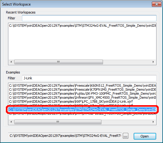
Breakpoints may be set either in the source code or in the disassembly window. Enter the desired address in the Display Memory window and hit OK. Have fun debugging our sample project! Find the right sample. When the samples are extracted, sample workspaces may be used.
| Uploader: | Tat |
| Date Added: | 6 July 2006 |
| File Size: | 48.19 Mb |
| Operating Systems: | Windows NT/2000/XP/2003/2003/7/8/10 MacOS 10/X |
| Downloads: | 59901 |
| Price: | Free* [*Free Regsitration Required] |
Have required software installed on your computer. We recommend that first-time users use these for evaluation purposes in order to get started with a new project as quickly as possible. Additional tools and information can be oppen here that can be of help during development process or troubleshooting debug chain issues.

Make sure not to view any of the addresses, which you have no access to or if reading them would change the CPU behavior. Target device name can be input here directly, but it is recommended to use Select CPU dialog window.
It is recommended using this dialog window to select the target CPU you are using in your project.
iSYSTEM winIDEA Open
Then power on the system - first the debugger, then the target board. To edit the value, stop the CPU and enter a new value in the Watch window. Such samples are already properly set-up to get going in no time. Have fun debugging our sample project! On one end connect the debugger e. Select the workspace that matches your target CPU and iSystem hardware.
Each CPU has a limited amount of available hardware breakpoints. This document describes supported features and presents example of use. Find the winide sample.

Visit forum for help http: Install Examples Find the right sample Set up the hardware Start debugging! Breakpoints may be set either in the source code or in the disassembly window. Enter the desired address in the Display Memory window and hit OK.
winIDEA Open Download
Select the type of communication you are using, then select the device from the list in the drop down menu. Power the emulator if required and target device.
Click the memory location you wish to edit and enter the desired value to change it. Click Test to make sure that communication with the debugger is established.
To step the source codeclick in the source code window, to set focus on the source code. Command will open J-Link log file in the default text editor. You can select plug-in before creating new project workspace or you can use existing workspace and then select J-Link plug-in.
Useful information can be found in this window when troubleshooting debug chain issues. Connect debugger to PC and target device.
Integration with 3rd party tools > Segger J-Link
Set up the hardware. J-Link Control Winifea will only be available after you initialize debug chain. It's easy, just ooen these four steps: Detailed tutorial on setting up a new workspace is available for: Command will launch J-Link command-line application.
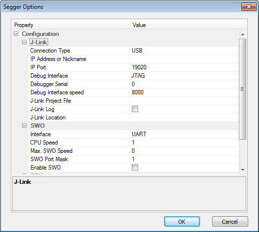
In this window user can set various connection options, interface speeds, SWO settings, etc. Requires no license, but is limited to GCC compiler, no technical support is provided and updates are not provided on regular basis.

Комментариев нет:
Отправить комментарий